Mixed Radix FFT IP Core for Xilinx FPGAs
Description
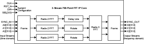
Dillon Engineering's Mixed-Radix FFT IP Core uses a modular combination of radix-2, -3, -5, and -7 Fast Fourier Transform (FFT) pipelined engines to provide discrete transforms on data frames or continuous data streams, with sample rate up to the maximum clock frequency. The engines are arranged to provide the most beneficial resource usage and data ordering for the system. The IP Core is further customized to support single- or multi-stream continuous throughput I/O, and any width fixed- or floating-point data.
Features
- Fast Fourier Transform (FFT) for non-power of 2 lengths.
- Any combination of radix-2, -3, -5, and -7.
- Run-time selectable length within superset
- Example mixed length: 32x3x5 = 480-point
- Run-time selectable Forward/Inverse transform mode
- Any width fixed- or floating-point
- Single- or multi-stream I/O
- Continuous processing performance
- See Table for 3-stream 768 point FFT.
- Customized for any order inputs and outputs
- Includes C/C++ bit-accurate model and data generator
- Model also usable from MATLAB
Block Diagram
Example Mixed Radix FFT IP block diagram:
Xilinx FPGA Resource Usage
Example Implementation Statistics for Xilinx FPGAs, Continuous 3-stream 768 point (256x3) FFT, 16-bit complex fixed-point.
|
Family |
Example Device |
Fmax (MHz) |
Slice FF1 |
Slice LUT1 |
IOB2 |
GCLK |
BRAM |
DSP |
|
Spartan®-3A |
XC3SD3400A-5 |
100 |
9,673 |
10,956 |
207 |
1 |
13 |
62 |
|
Virtex®-4 |
XC4VSX55-12 |
180 |
10,435 |
11,842 |
207 |
1 |
13 |
62 |
|
Virtex®-5 |
XC5VSX50T-3 |
240 |
10,935 |
12,722 |
207 |
1 |
8 |
62 |
Notes:
1) Actual slice count dependent on percentage of unrelated logic – see Mapping Report File for details
2) Assuming all core I/Os and clocks are routed off-chip
1) Actual slice count dependent on percentage of unrelated logic – see Mapping Report File for details
2) Assuming all core I/Os and clocks are routed off-chip
Additional Information
For additional information view the Mixed Radix FFT Datasheet
Fill out the Mixed Radix FFT IP Fit/Information Form to obtain a device usage estimate for another target technology or to obtain additional information about the Mixed Radix FFT IP Core.
Xilinx site listing for Mixed Radix FFT Candidate Core.